This is the second of a series of posts on constructing your own 3D Printer. If you’re coming late to the party, you should check out the first post.
I assume you have all the necessary parts in front of you, and the necessary dose of excitement and patience to assemble them all into a cohesive, functioning machine. We’ll break down the construction into these elements:
- Mechanical Frame
- Electrical/Motors
- Neural
- Power Supply
Before you begin, you would need these basic tools:
- A set of Allen Keys
- Screwdriver
- Kapton Tape
- Electrical Tape
- Soldering Kit
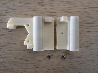
Also, here’s a picture of all the printed parts that you will be using, and an identifier table:
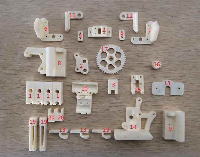
| ID Number | Part Name | Number of Parts | Revised Parts |
| 1 | Chassis Corners | 4 | |
| 2 | Y Motor Mount | 1 | |
| 3 | Y Idler | 1 | |
| 4 | Y Belt Holder Assembly | 1 | |
| 5 | Y Belt Holder Assembly | 2 | |
| 6 | Z Left Bottom | 1 | |
| 7 | Z Right Bottom | 1 | |
| 8 | X Motor Mount | 1 | |
| 9 | X Idler | 1 | |
| 10 | X Carriage | 1 | |
| 11 | Z Right Top | 1 | |
| 12 | Z Left Top | 1 | |
| 13 | End Stopper Mount | 3 | |
| 14 | Wade’s Extruder Body | 1 | Direct Drive Assembly |
| 15 | Wade’s Extruder Idler | 1 | |
| 16 | Wade’s Extruder Small Gear | 1 | |
| 17 | Wade’s Extruder Big Gear | 1 | |
| 18 | Hot End Mounting Plate | 1 | Aluminium Hot End Mounting Plate |
| 19 | Filament Mount Assembly 1 | 2 | |
| 20 | Filament Mount Assembly 2 | 2 |
You can see above that I have replaced the Wade’s extruder design with what is known as a Direct Drive extruder, which is much simpler, and in my opinion, works better than the Wade’s Extruder. Also, having a hot end mounting plate made with plastic seemed silly in retrospect. I went from feeling silly to disheartened when I saw the mounting plate bend and warp under the constant, near-200-degrees heat of the hot end. For this reason, I quickly improved that part of the assembly to a laser cut aluminium mounting plate, which has worked flawlessly. In this post, I will stick to the status quo and guide you through the construction steps ‘as is’, without discussing these revisions. Later, for sake of clarity, I will add another post that will just talk about all the revisions I have made to the printer.
Now, let’s dive in.
Mechanical Frame
Building the Chassis.
1. Assemble the Port and Starboard sides of the Chassis.
| Required Parts | Number |
| Printed Chassis Corners (no. 1)* | 4 |
| 380 mm M8 Threaded Rod | 2 |
| 350 mm M8 Precision Rod | 2 |
| Fender Washer | 4 |
| LM8UU Bearing | 3 |
| M8 Nut | 12 |
| M8 Washer | 8 |
*1 – The number here points to the identity of the printed part. Check the first table in this post, and the corresponding image to find the correct part.
- Hold the printed chassis corners with the semi-circular opening facing upward and inward.
- Put 2 LM8UU bearings on one 350mm precision rod on the port side, and 1 LM8UU on the starboard side.
- Slide the precision rods into the semi-circular slots of the printed chassis corners. This step might require some force. Make sure the precision rods are meeting the ends of the slot. An optional step is to apply zip ties through the holes on the plastic corners to hold down the precision rods.
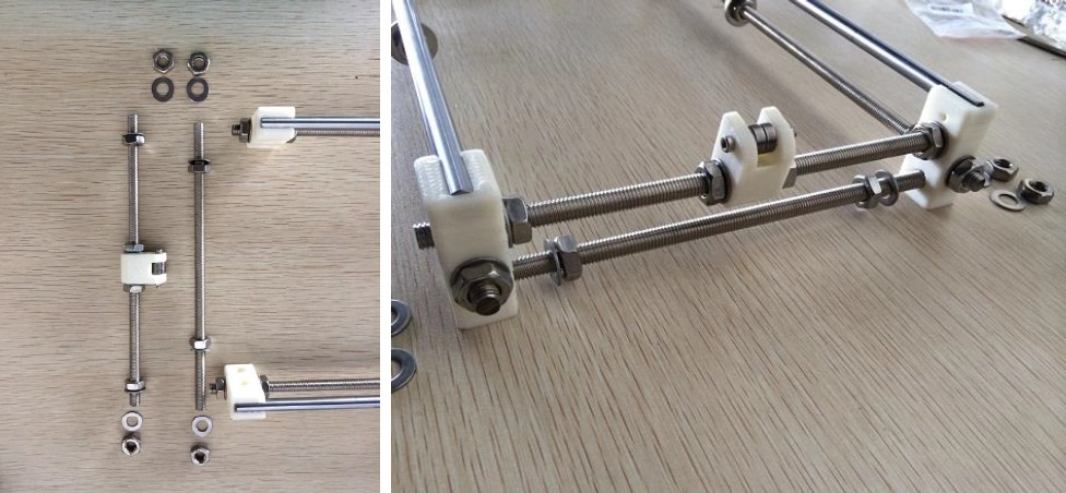
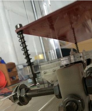
- Slide the 380mm threaded rods through the chassis corners right beneath the precision rods. Put m8 nuts, m8 washer, and m8 fender washers on the threaded rods in the following order:
m8 nut – m8 washer – chassis corner – m8 washer – m8 nut – m8 nut – m8 fender washer – m8 fender washer – m8 nut – m8 nut- m8 washer – chassis corner – m8 washer – m8 nut (see pictures below). - Be sure to follow the order off the nuts/washer. If you are something like this for the first time, it is quite a dance.
- Tighten the nuts.

Be sure to follow the order of the nuts and washers. Also note that the top assembly is on the port side, and the bottom assembly goes to the starboard.
2. Assemble the Y Idler
| Required Parts | Number |
| 623ZZ Bearing | 2 |
| Printed Y Idler (no. 3) | 1 |
| M3-25 Screw | 1 |
| M3 Nut | 1 |
- Put the M3-25 screw through the printed Y Idler piece, with two 623ZZ bearings in between. Lock the other end with an M3 nut.

3. Assemble the Front and Back of the Chassis.
| Required Parts | Number |
| 205mm M8 Threaded Rod | 3 |
| 310mm M8 Threaded Rod | 1 |
| Printed Y Motor Mount (no.2) | 1 |
| Assembled Y Idler | 1 |
| M8 Nut | 26 |
| M8 Washer | 22 |
| M8 Fender Washer |
4 |
Note: The easiest way to put these nuts and washers is to slide the inside ones first, then sandwich the rod between two chassis corners, and then put the outside nuts and washers.
- Put m8 nuts, washers, and assembled Y idler on a 205mm m8 threaded rod. Slide this rod through the top holes of the front chassis corners. The order is:
nut – washer – chassis corner – washer – nut – nut – washer –assembled Y idler – washer – nut – nut –washer – chassis corner – washer – nut. - Do not tighten yet.
Repeat the previous step without the Y idler, and fix the rod on the bottom holes of the chassis corner. The order is:
nut – washer – chassis corner – washer – nut – nut – washer – chassis corner – washer – nut. - Do not tighten yet.
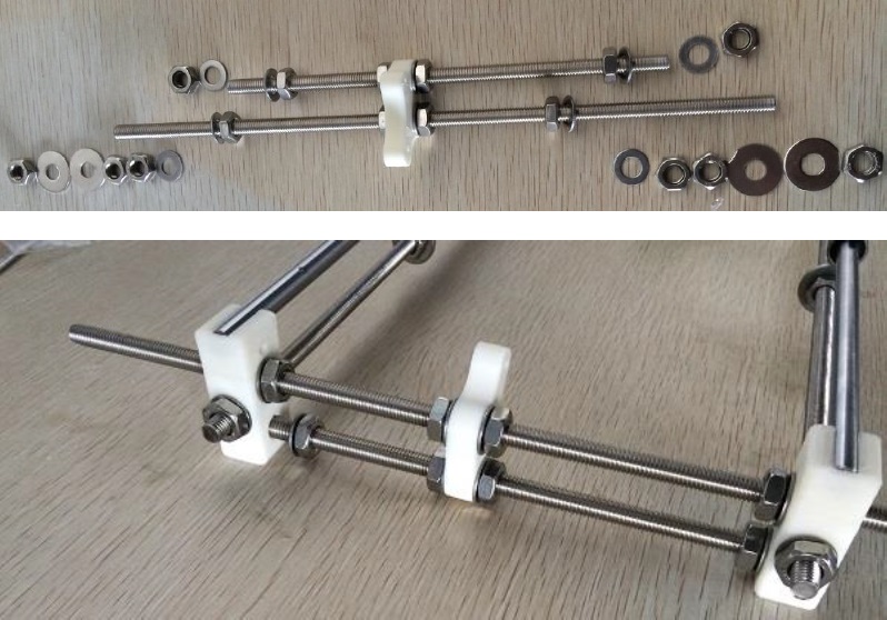
- Next, Put the 310mm and 205mm rods through the printed Y motor mount, with orientation shown in the picture above. The 310mm should be going through the top holes in the chassis corners. The order of washers and nuts on the 310mm rod is:
nut – fender washer – fender washer – nut – nut – washer – chassis corner – washer – nut – nut – washer – Y motor mount – washer – nut – nut – washer – chassis corner – washer – nut – nut – fender washer – fender washer – nut. The order of nuts and washers on the 205mm rod is: nut – washer – chassis corner – washer – nut – nut – washer – Y motor mount – washer – nut – nut – washer – chassis corner – washer – nut. - Do not tighten yet.
- Align the rods and tighten all nuts so the chassis will not fall apart.
- You might need to adjust the chassis later when mounting the Y plate.
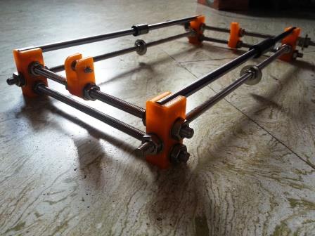
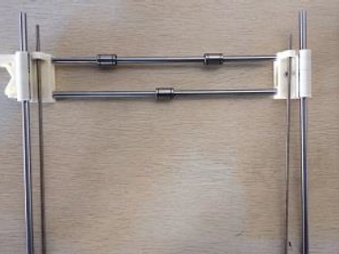
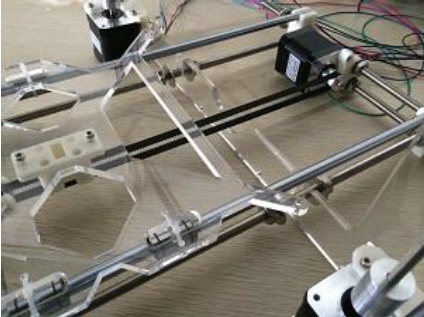
Congratulations, your Chassis is now complete. It should look something like this:
Attaching the Y Plate.
| Required Parts | Number |
| Acrylic Bed* | 1 |
| M3-16 Screw | 6 |
| M3 Nut | 6 |
| Y Belt Holder Assembly 1 (no.4) | 1 |
| Y Belt Holder Assembly 2 (no.5) | 2 |
| M3-10 Screw | 2 |
| Zip Ties | 3 |
| GT-2 Timing Belt | ~70 cm |
| Nema 17 Motor | 1 |
| GT-2 20 Teeth Pulley | 1 |
* – Your ‘Bed’ may or may not be made of Acrylic. You may have chosen to acquire an aluminium or an all steel frame. Either way, this is purely a matter of choice. However, your choice may affect the stability and strength of the printer. There are printers out there with high-density cardboard frames, but I don’t really know what kind of strength they can provide to the printer, and what kind of vibrations they can withhold. For our purpose here, let’s stick to Acrylic.
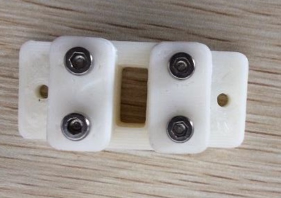
- Insert four M3 Nuts into the hexagonal slots in the Y Belt Holder Assembly 1.

- Loosely attach the two rectangular pieces to the main piece using four M3-16 screws. Make sure the flat surface is facing outward.
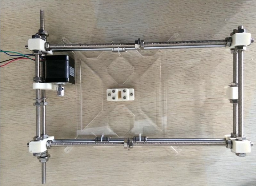
- Attach the acrylic Y bed to the chassis using 3 zip ties over the LM8UU bearings. Make sure the bed slides freely on the chassis. Also attach a Nema 17 motor to the Y Motor Holder using two M3-10 screws, and attach a GT2 20 Teeth Pulley on the motor’s shaft.
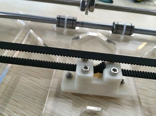
- Attach the Y Belt Assembly to the Acrylic Bed using two M3-16 screws and two M3 nuts. Take 70cm of GT2 timing belt and insert one end into the Y belt holder. Tighten the two M3-16 screws to hold down the belt.

- Wrap the GT2 Timing Belt around the Y motor’s Aluminum Pulley, and around the 623zz bearings. Insert the other end of the GT2 Timing Belt into the Y Belt Holder and tighten the M3-16 screws. The belt should be tight with tension. As the bed moves on the chassis, there should be no skipping.
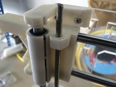
Building the X – Z Axes
| Required Parts | Number |
| Printed X Idler (no.9) | 1 |
| Printed X Motor Holder (no.8) | 1 |
| Printed X Carriage (no.10) | 1 |
| 370mm 8mm Precision Rod | 2 |
| LM8UU Bearings | 7 |
| M5 Nut | 2 |
| Zip Ties | 8 |
| Nema 17 Motor | 1 |
| GT20 20 Teeth Pulley | 1 |
| M3-16 Screw | 3 |
| GT-2 20 Teeth pulley | 1 |
| GT-2 Timing Belt | 90 cm |
| M3-20 Screw | 1 |
| 623zz Bearing | 2 |
| M3 Nut | 1 |
| 300mm M5 Threaded Rod | 2 |
| 320mm 8mm Precision Rod | 2 |
- Insert two LM8UU bearings into the x idler and the x motor holder. A little force is required to push the bearings in.

- Insert the M5 nuts into the hexagonal slots on the X idler and the X motor holder. These two nuts must be tightly held in the slots for proper z movement. If you find the two nuts falling out of place during z movement, heat the nuts on fire and insert hot M5 nuts into the hexagonal slots. The heat will melt the ABS a bit and provide a tight fit.
- Use the M3-20 screw and nut to attach two 623zz bearing to the X idler.

- Screw the two 300mm M5 threaded rod through the M5 nuts. If you feel the nuts coming slipping from their slots, that means you need to heat them again. Make sure the nuts fit tightly in their slots before attempting this step.

- Attach the two 370mm 8mm precision rods with three LM8UU bearings.

- Attach the two 320mm 8mm precision rods through the LM8UU bearings.
- Attach the Nema 17 motor to the printed X Motor Holder using three M3-16 screws. Attach a GT20 aluminum pulley to the motor’s shaft.
- Attach the X carriage to the x axis using 6 zip ties. The X carriage should sit tightly on the LM8UU bearings.

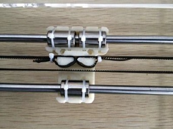
- Wrap the GT20 timing belt around the X motor and the 623zz bearings. Tie both ends to the X carriage using zip ties. Make sure the belt is tight and there is no skipping when the carriage moves.
Building the X – Z Plate
| Required Parts | Number |
| Acrylic Main Frame | 1 |
| Acrylic Side Panels | 2 |
| Nema 17 Motor | 2 |
| Z Left Top (no.12) | 1 |
| Z Right Top (no.11) | 1 |
| Z Left Bottom (no.6) | 1 |
| Z Right Bottom (no.7) | 1 |
| M3-16 Screw | 10 |
| M3 Nut | 16 |
| M3-10 Screw | 6 |
| Motor Coupler | 2 |
| M3-25 | 6 |
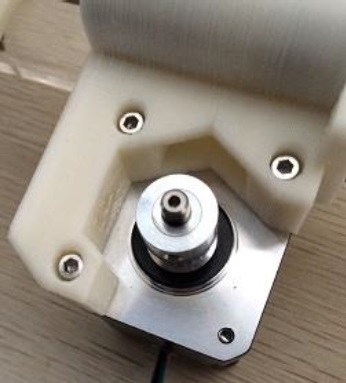
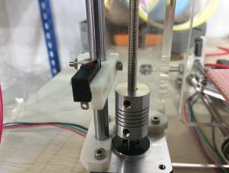
- Attach the Z Left Bottom and Z Right Bottom pieces to the Acrylic Plate with three M3-16 screws each. Then attach two Nema 17 motors to the Z Left and Z Right pieces with three m3-19 screws each. Attach a motor coupler to each motor. Make sure the wires from the Nema 17 motors go through the bottom openings on the Acrylic Plate. Do not attach the top Z pieces yet.

- Attach the X-Z system assembled in the previous section to the Z plate. The precision rods of the X-Z system should fit into the circular openings on the Z Bottom pieces. The precision rods then sit right on top of the Z motors (you might need to gently hammer the rods for them to go all the way in). The threaded rods should fit into the motor coupler. Slide the X printed pieces on the precision rods to make this fit happen.
- Attach the Z Top pieces to the Acrylic Plate with two m3-16 screws and nuts on each side.
- Attach the finished X-Z plate to the chassis. The X-Z plate should be sitting between the two fender washers on the chassis. Do not tighten the nuts yet.
- Attach the side panels to the main acrylic frame using three M3-25 and three M3 nuts on each side.
- Place the side panel with holes on the starboard side (the side with X motor). Place the bottom slot of the side panel between the fender washers on the longer rear threaded rod.

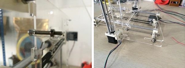
- Right about now, your 3D Printer should be looking like this:

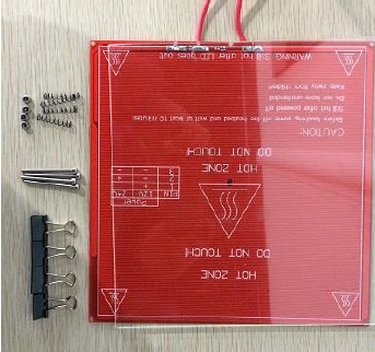
Attaching the Heat Bed.
| Required Parts | Number |
| MK2A HeatBed | 1 |
| Borosilicate Glass | 1 |
| Spring | 4 |
| M3 Locking Nut | 4 |
| Paper Clip | 4 |
| M3-30 Screws | 4 |
- Attach the borosilicate glass to the MK2A heatbed with paper (Binder) clips. Try and place the binder clips in the extreme corners of the print area when you clip them on the glass and heatbed.
- Attach the heatbed to the acrylic bed using M3-25 screws, springs, and M3 locking nuts. The order is:
M3-25 screw – Heatbed – spring- Acrylic Bed – M3 locking nut. - Repeat this for all four corners.
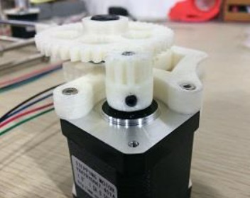
Assembling the Wade’s Extruder.
A note before we proceed: As mentioned at the start of this (long) post, I started out with a standard Wade’s Extruder before chucking it and moving to a Direct Drive Extruder. I have nothing against the Wade’s Extruder, but it just didn’t work for me. The plastic gears failed to squeeze the filament through the hotend at the right speed and amount, which is bad when you’re trying to calibrate the ‘Extruder Steps’ to a high accuracy (we will learn later what extruder steps are and how to calibrate them). In the same breath I want to say that this doesn’t mean Wade’s Extruder won’t work for you. If it doesn’t, or if you just want to move to the simplicity of a Direct Drive Extruder, I will speak about it in the ‘Revisions’ post that I’ve promised. Until then – onward!
| Required Parts | Number |
| Printed Extruder Main Body (no.14) | 1 |
| Printed Extruder Idler (no.15) | 1 |
| Printed Big Gear (no.16) | 1 |
| Printed Small Gear (no.17) | 1 |
| Printed Mounting Plate (no.18) | 1 |
| 608zz Bearing | 3 |
| M3-40 Screw | 2 |
| M3-50 Screw | 2 |
| M8 Hobbed Bolt | 1 |
| M8 Locking Nut | 1 |
| M3 Nut | 8 |
| M3-25 Screw | 2 |
| M3 Thumb Screw | 1 |
| M3-30 Screw | 1 |
| M8 Washer | 5 |
| Nema 17 Motor | 1 |
| M8 Threaded Rod 2 cm | 1 |
- Attach one 608zz bearing to the Idler using the M8 2cm Threaded Rod. To insert the rod, you need to give it a gentle push, which could be accomplished with a pair of pliers.
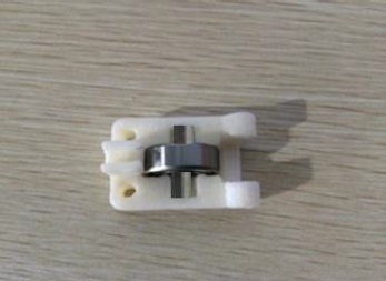
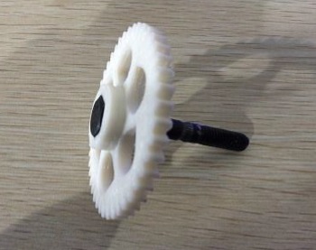
- Insert the M8 Hobbed Bolt into the Big Gear.
- Attach two 608zz bearings to the extruder’s main body.
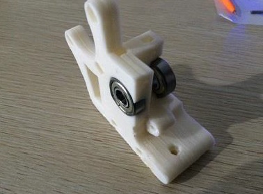
- Attached the Big Gear with Hobbed Bolt to the Extruder’s Main Body. Insert M8 washers to make the teeth on the Hobbed Bolt right above the filament opening (this will take some trial and error). Lock the M8 Hobbed Bolt on the other side with a M8 locking nut. Attach the Idler to the main body using M3-30 screw and M3 nut.

- Insert one M3 nut into the small gear. Put the small gear on the Nema 17 motor’s shaft, and lock with a M3 thumbscrew (take one of the x motor’s aluminum pulley, and make sure the other thumbscrew on the pulley sit directly on the flat side of the motor’s shaft). Attach the motor to the Extruder’s main body using 3 M3-10 screws. Once you do this, try spinning the gears and see if they correlate.
- Attach the finished Extruder assembly to the X carriage using two M3-50 screws. Insert two M3 nuts on the back of the X carriage.

- Finally, use the Printed Mounting Plate (no.18) and two M3-16 Screws and two M3 nuts to mount your J-Head HotEnd. I think this is where I must strongly suggest you to chuck the plastic mounting plate and go with an Aluminium plate. You can find one on eBay. If you do this now, it will save you a lot of angst later. Plastic Mounting plates are silly, especially if you want to be printing with ABS.
Attaching the End Stoppers.
| Required Parts | Number |
| Printed End Stopper Mount (no.13) | 3 |
| End Stopper | 3 |
| Zip Ties | 6 |
| M3-25 Screw (optional) | 3 |
| M3 Nut (optional) | 3 |
- Attach the end stoppers to the end stopper mounts using zip ties. Wrap zip-ties around the two holes on the end stopper mount and the two holes on the end stopper. Cut off the excess zip-ties.

- Attach the end stopper mounts to the Starboard side of the Z precision rod, to the X precision rod near the X Motor Mount, and to the Starboard side of the Y precision rod towards the back. Tighten each end stopper with a M3-25 screw and a M3 nut. If you find this hard to achieve, simply use zip ties to attach the Endstopper Holder to the 8mm precision rods.


If you’ve read, followed, understood and acted upon all the steps mentioned above, you should have yourself a fully built mechanical frame. Right about now, you are missing a lot of nuts and screws (not just in your brain), you are exhausted, but you also have a goofy smile on your face as you look lovingly upon your (half-built) 3D Printer.
We have a long way to go before the thing actually starts to move, and a lot further before it prints. Until then, go take a break, and meet me back here for the ‘Electrical‘ element of the build.
*

Leave a comment