
Sparking to Life
In this post, let’s discuss how you’ll bring the inert frame of your 3D Printer to life. If you study your printer as it is right now, you will observe a number of wires heading out listlessly from the 5 stepper motors, from the hotend, and from the PCB Heat Bed, along with wires that will soon head out from the three Mechanical End Stops that you will be wiring in this post. Let’s take a look at the components we will need for this part of the build, and get right into it.
| Required Parts | Number |
| Arduino Mega 2560 | 1 |
| RAMPS 1.4 Shield | 1 |
| Pololu Stepper Drivers | 5 |
| Heat Sink | 5 |
| Mechanical End Stops | 3 |
| Power Supply Unit | 1 |
| Jumpers | 15 |
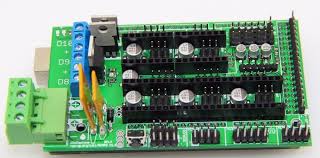
Inserting Jumpers to RAMPS 1.4
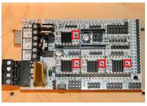
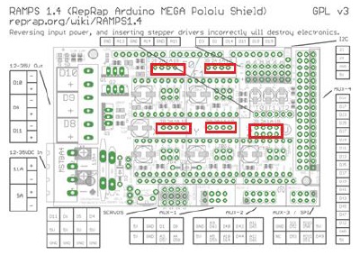
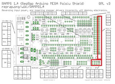
A Jumper is a short length of conductor used to break in or open, or bypass part of, an electric circuit. Jumpers control the precision of the motor movement. To have the most precise stepping (1/16 micro-stepping), insert three jumpers to each of the areas outlined in this picture of the RAMPS 1.4 shield:


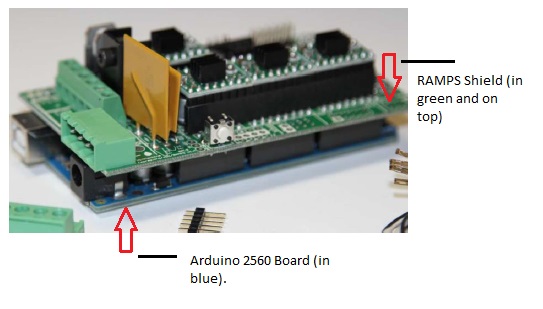
Connecting the Boards
Stack the RAMPS 1.4 Shield on top of the Arduino Mega 2560 Board. The orientation of the boards while stacking them is shown below:
Next, stack the Pololu Stepper Motor Drivers on top of the RAMPS 1.4 shield. Be sure to orient the Stepper Drivers and insert them in the proper direction (as shown below). There have been many cases of the Stepper Drivers being fried because of incorrect orientation. The Potential Meter on the Stepper Motor Drivers should be facing away from the ‘D8-D9-D10’ area on the RAMPS.

Install the Heat Sinks that are provided with the Stepper Drivers on top of the Stepper Drivers. Make sure the heat sink are not touching multiple components on the drivers. This can be tricky, but is achievable.
Crimping the Connectors
I’ve noticed these days that 3D Printer kit manufacturers/sellers send out kits with the wires already crimped to their connector housings, and therefore, ready to connect to the Shield. However, if this is not the case with the parts you obtained (as it was with mine), you have to learn the nifty little skill of crimping wires and inserting them into plastic housings known as connectors, after sheathing them in aluminium crimps. If you are unfamiliar with this, here’s a guide on crimping that I found useful.
When crimping the stepper motor wires, follow the black–green–blue–red order for the wires. If you find the motor spinning in opposite direction later, switch off the printer, disconnect the connector and flip it over.
Note: The Thermistor wires, running from the hotend and the heat bed (and usually white in color), do not have any particular orientation.
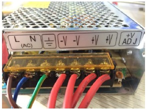
Connecting the Power Supply
Cut the end of your power cord (if it not included in the kit – this is the case many times – you may use a cord similar to the one that powers your desktop computer) to reveal three wires: Brown, Blue, Green. If you get a different set of colors, use a multi-meter to determine the L, N and G nodes. Strip the wires and connect them to your power supply unit’s L, N and G nodes, respectively. Like so:
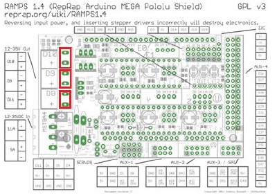
Get four spare wires and connect two to the V+ nodes and two to the V- nodes. Connect the other end of these wires to the RAMPS shield’s input nodes:

Connecting the Rest.
The rest of the parts: The 5 stepper motors, the 2 Thermistors (from the hotend and heatbed), the Hotend, the Heatbed, and the Fan all connect to the shield in the configuration shown below:
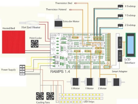
Let’s go through the individual connections step by step.
Stepper Motors & Extruders
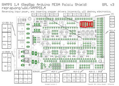
If you’ve crimped all the stepper motor wires, you should have five housings of four wires each in this configuration: black–green–blue–red. Insert the five connector housings here, and in this specific order:
Thermistor
The Thermistor wires from the HotEnd and the HeatBed go here:

Insert the thermistor from Extuder 1 to the rightmost pin, the wire from the heatbed next, and if you have a second extruder, the thermistor from it should be inserted into the left-most pin.
Heating
Insert the Heater wires (usually in red) from Extruder 1 to D10 of the RAMPS Shield, the heater wires from the heatbed to D8, and you can use D9 to power a fan or a second extruder.
End-Stops
The mechanical end-stops are polarity sensitive. Solder wires (you can just twist the wires around the metal brackets of the end-stops if you are unable to solder them) to the ‘COM’ and ‘NC’ leads. Connect these two leads to the top two rows in the end-stop area outlined below, with NC on the top and COM on the bottom.
From left to right, each column corresponds to xmin, xmax, ymin, ymax, zmin and zmax outputs of the end stops. If you are using optical end stops, use all three pins. You will only need to connect all max or all min end stops. The other limit will be specified in the firmware.
LCD Controller
This is optional, but useful. Connect your LCD to these pins on the RAMPS:
With everything connected, I am sure you are eager to get the printer up and running. However, while the printer is electrified now, we do not have any way to command and control the printer. For this, we will explore how to interact with the printer using a firmware and interface software, in the next post.
*-*

Leave a reply to Building a 3D Printer – Mechanical | Rohit Nalluri Cancel reply